WEEK 1
Nuke 3D and Camera Projection
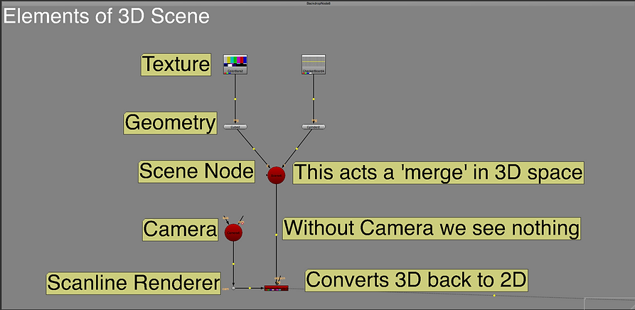
This week we looked at the basic tools used in a 3D scene within Nuke. Below are some of the key feature discussed.
WEEK 2
Nuke 3D Tracking
Tracking
Started by creating a roto shape around the houses in the clip avoiding the water as we will be tracking. Below the tracking markers can be seen in green after removing all the non-viable tracks.
Script
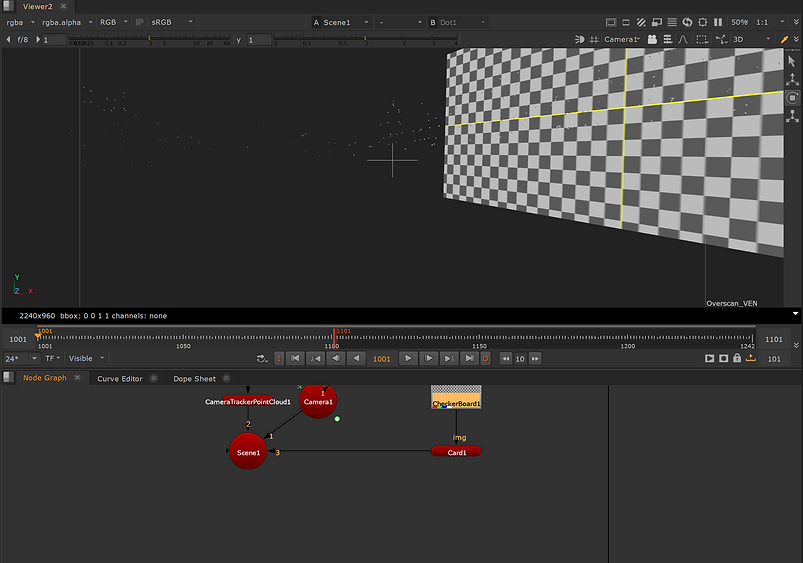
Adding in a camera tracker creates this section of the script automatically. Creating the two camera set ups ready to be used in the 3D space.

Point Cloud
The tracking markers made previously become the point cloud in the 3D space viewer as seen below. This shows the scale and placement of the buildings rotoscoped before.

Card
I then placed a card (equal to a 'plane' in Maya). The card will be used to project the texture on to over the building later on. The trackers mean the card will follow the line of the camera.

Texture
Here I applied a checkboard texture just to check the process has worked.
Script
Here I copied the script from before and made a second version to start the roto paint process of removing the window I tracked earlier. Below shows the additional nodes added to complete the next steps.

Roto
I rotoscoped around the window to remove it from the image and rotopainted over the area to blend in with the surrounding wall.
Before
Before the window was removed.

After
Final image without the window being visible.

WEEK 3
3D Equalizer Overview
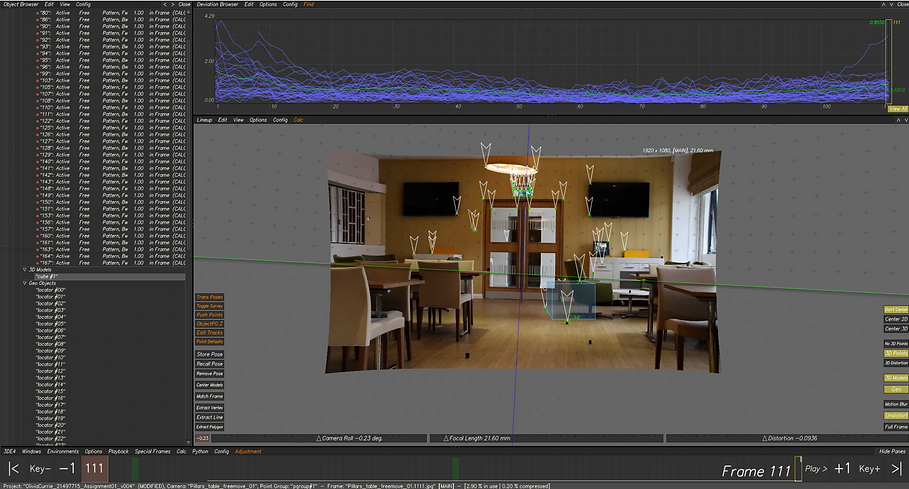
This week we went over the basics of how 3D Equalizer works. We used the below image as reference for where to place the trackers in the scene. Once all the trackers were done, I created locators to define where the tracking points are. This then translates into the 3D space where the 3D object can then be placed as seen below. The final number on the deviation was 0.09 (the aim to be below 2.0).

Locators in 2d Space
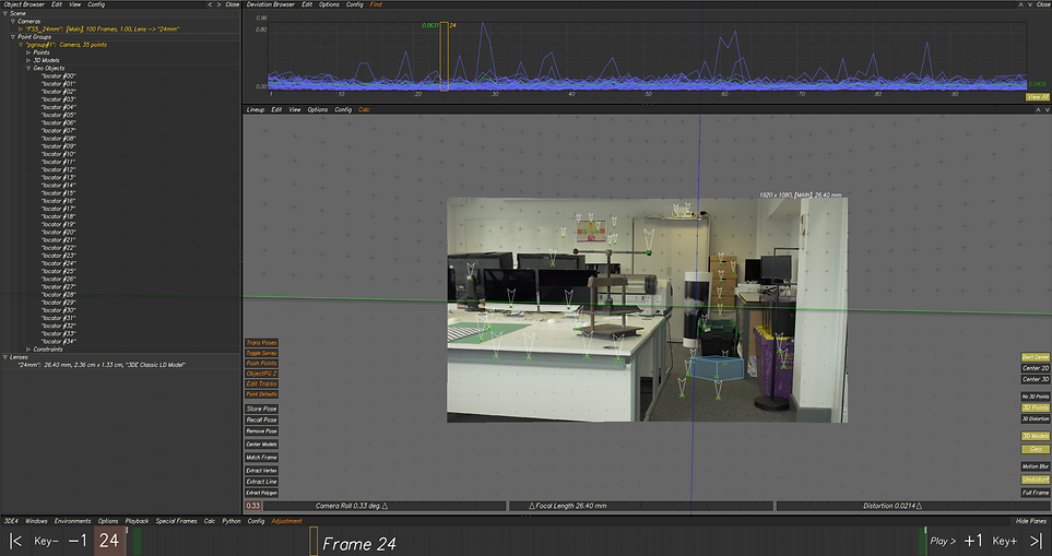


3D Space Point Cloud
Final Figure
WEEK 4
Cameras and Lenses
- Cameras refers to an image sequence or plate in 3DE.
- Lens refer to a pairing of a camera and lens in 3DE.


WEEK 5
3DE Free-flow and Nuke
Covering the pipeline of how to take the data from 3DE, such as cameras, objects and lens distortion into Nuke. Then how to create a script in Nuke to removed and reapply lens distortion to make the 3D objects fit the 2D scene.
Creating Locators

Adding the Cube
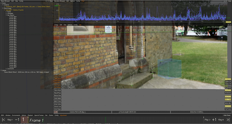
Importing Data into Nuke

Creating the Camera
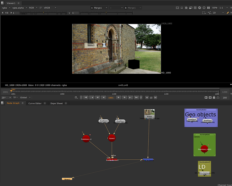
Node Graph with Distortion Application


Roto Shape and Paint

Adding the Card
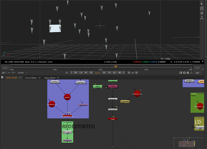
Final Image with Locators (sign removed)

Full Script for the Whole Process

WEEK 6
Surveys
This week we looked at surveys in 3DE. The process of adding extra tracking information to the sequence by tracking on the references images first, then projecting the tracks on to the main sequence.
Creating the individual points
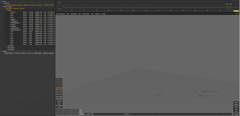
Showing the ref images in outliner

Tracking point on one of the ref images

Assignment 01
Reference Image

3DE
Tracking Markers
Lineup View (tracks)
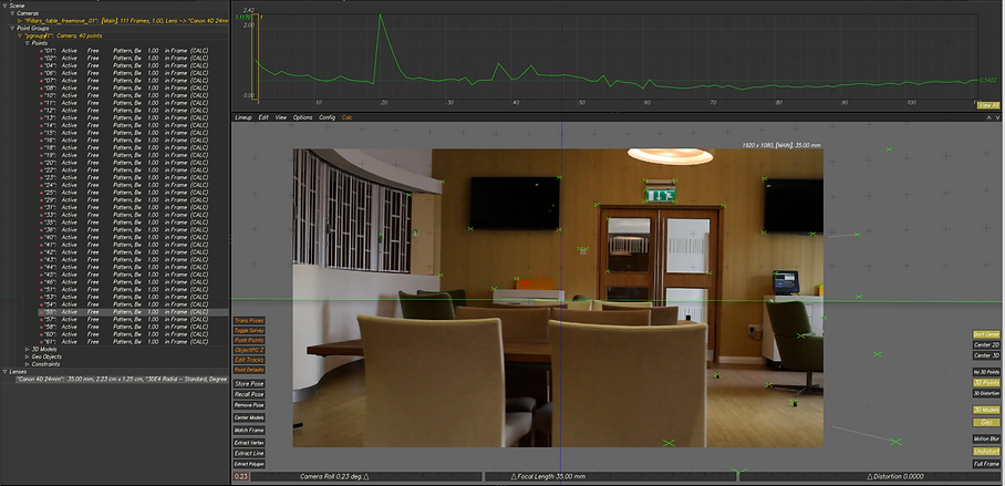
Deviation Browser

Final Deviation & Point Cloud

Lens Data
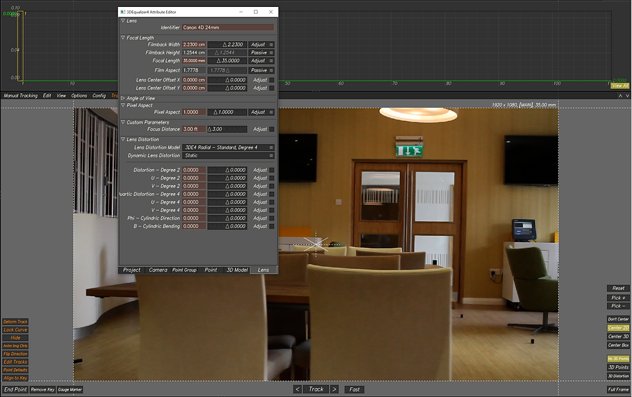
Lens Parameter

Lens Distortion

Locators
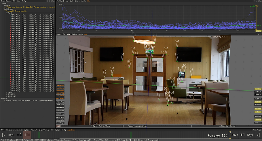
3D Object
